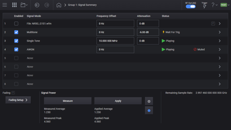
If you have Option 8SG, eight virtual signal generators (multiple IQ paths to RF), clicking the Signal block opens the Signal Summary screen, displaying all your current generated or downloaded waveforms, including status information for each. You can also enable or disable playback for each waveform. Clicking a waveform row opens the Signal block configuration screen where you can edit settings and enable other features. Click Group 1: Signal Summary in the user-interface path (breadcrumbs) area to return.
For instruments with Option 8SG, eight signals are available to be summed at the output of the signal block. Each signal is limited to the optioned sample rate, and the total sample rate is limited to 3 GSa/s. For example, if your instrument’s channel has bandwidth Option B5X, each signal can have up to 600 MSa/s, but the total of the sample rates for all eight of the signals must be less than or equal to 3 GSa/s. If five signals have 600 MSa/s each, then no further signals can be turned on, as the total will sum to 3 GSa/s. Once you have configured signals that consume the total sample rate, you cannot configure additional signals.
If you do not have Option 8SG, clicking the Signal block takes you directly to the Signal block configuration screen.
If you have Option 8SG, waveform files assigned to the same signal group must have unique file names. The ARB waveform memory references the file name alone and does not distinguish between different directories. For more information, refer to ARB Waveform Memory.
Whenever you enable a particular waveform file that is not currently enabled in another IQ path, it uploads prior to playback. If the file is already enabled in one or more other IQ paths, an upload does not occur and the waveform plays directly.
If you update the IQ data for a particular waveform file, you must first disable the IQ paths where the old version of the same file is being used so that it uploads, replacing the old data.
For instruments with Option 8SG, in a multi-signal configuration, the correlation between each signal is unknown. The signal generator assumes that each signal is uncorrelated, which can result in inaccurate total RF power when that assumption is not true. This function provides a measurement by the instrument’s internal circuitry of the summed signal magnitudes, translates the result to the RF calibration plane, and provides results. This is intended to provide you with an indication of the power, accounting for any potential correlation of the enabled signals.
The measurement is performed on the sum of the vector modulation, if the instrument has Option 403 and AWGN or CW Interferer are enabled, the measurement includes these adjustments to the signal.
Performs a measurement of the power provided by the signals. A signal must be enabled to participate in the measurement. A measurement should be performed after all signals for your measurement scenario have been enabled, and again after you alter any signal by playing a different waveform or adjusting any of the signal’s settings, e.g. RMS, power, frequency offset, etc.
After a successful measurement, the instrument will display the Average Signal Power, the Peak Signal Power, and allow you to apply the measurement to the vector modulation. See Apply Signal Power.
|
SCPI Command |
[:SOURce]:GROup<group>:SIGNal:MPOWer? |
|
SCPI Example |
GRO:SIGN:MPOW? |
|
Notes |
The return value from the query is 0 if the measurement is successful, 1 if the measurement fails. If the measurement fails a Warning message will be posted to the status line: "Measurement of signal power failed, check each signal’s settings and perform measurement again" For instruments without Option 8SG, invoking this query will result in 1 being returned with no message posted to the status line. For instruments with Option 8SG, but the configuration uses a single signal (such as Channel Bonding), invoking this query will result in 1 being returned with no message posted to the status line. |
|
State Saved |
No |
|
Initial S/W Revision |
A.12.00 |
Query the status of the measurement. The possible values are:
|
Measurement Status |
Description |
|---|---|
|
IDLE |
The measurement is not currently running. |
|
INProgress |
The measurement is currently in progress. |
|
SUCCess |
The measurement completed successfully. |
|
NOData |
The measurement completed without doing any measurement, likely because there were no signals actively playing. |
|
FAIL |
The measurement failed. |
|
SCPI Command |
[:SOURce]:GROup<group>:SIGNal:MPOWer:STATus? |
|
SCPI Example |
GRO:SIGN:MPOW:STAT? |
|
State Saved |
No |
|
Initial S/W Revision |
A.12.00 |
After a successful Measure Signal Power has been performed the value of the Average Signal Power can be obtained. The value is in dBm. The value is reset to the default value when all signals have been disabled, or a Measure Signal Power has failed.
|
SCPI Command |
[:SOURce]:GROup<group>:SIGNal:MPOWer:AVERage? |
|
SCPI Example |
GRO:SIGN:MPOW:AVER? |
|
Notes |
If the SCPI query is performed with the measurement results in their default values the return value is NaN. |
|
State Saved |
No |
|
Initial S/W Revision |
A.12.00 |
After a successful Measure Signal Power has been performed the value of the Peak Signal Power can be obtained. The value is in dBm. The value is reset to the default value when all signals have been disabled, or a Measure Signal Power has failed.
|
SCPI Command |
[:SOURce]:GROup<group>:SIGNal:MPOWer:PEAK? |
|
SCPI Example |
GRO:SIGN:MPOW:PEAK? |
|
Notes |
If the SCPI query is performed with the measurement results in their default values, the return value is NaN. |
|
State Saved |
No |
|
Initial S/W Revision |
A.12.00 |
After a successful Measure Signal Power has been performed you can apply the result to the vector modulation, this allows the instrument to compensate for correlation which may occur from your scenario of multiple signals.
|
SCPI Command |
[:SOURce]:GROup<group>:SIGNal:MPOWer:APPLy |
|
SCPI Example |
GRO:SIGN:MPOW:APPL |
|
Notes |
Sending the SCPI command with the measurement results in their default values raises the error “-200, Execution Error; Perform Measure Signal Power before applying the result. |
|
State Saved |
No |
|
Initial S/W Revision |
A.12.00 |
After an Apply Signal Power has occurred, the Average Power value applied is captured and displayed. You can use this to compare a subsequent Measured values to the currently applied values. The value is in dBm. The value is reset to the default value when all signals have been disabled.
|
SCPI Command |
[:SOURce]:GROup<group>:SIGNal:MPOWer:APPLied:AVERage? |
|
SCPI Example |
GRO:SIGN:MPOW:APPL:AVER? |
|
Notes |
If the SCPI query is performed when the Apply has not been performed the return value is NaN. |
|
State Saved |
No |
|
Initial S/W Revision |
A.12.00 |
After an Apply Signal Power has occurred, the Peak Power value applied is captured and displayed. You can use this to compare a subsequent Measured values to the currently applied values. The value is in dBm. The value is reset to the default value when all signals have been disabled.
|
SCPI Command |
[:SOURce]:GROup<group>:SIGNal:MPOWer:APPLied:PEAK? |
|
SCPI Example |
GRO:SIGN:MPOW:APPL:PEAK? |
|
Notes |
If the SCPI query is performed with the measurement results in their default values the return value is NaN. |
|
State Saved |
No |
|
Initial S/W Revision |
A.12.00 |
There are various settings available to configure the Signal Power measurement. For example, you can configure how long the Signal Power measurement will run.
You can access these settings by clicking the  icon displayed in the Signal Power section of the Signal Summary screen. Clicking this icon opens the Measure Power Config screen displaying the available configuration options.
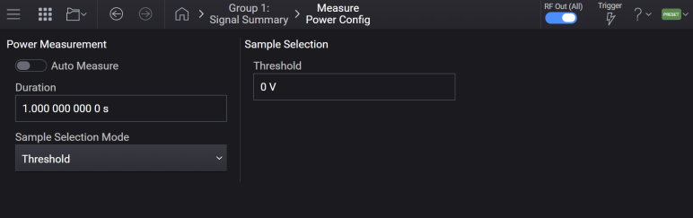
When you enable this option, the Signal Power measurement will be automatically run any time a signal is Enabled or Disabled. In addition, when the measurement completes, the updated values will be applied and used. This is equivalent to manually performing a measurement and applying signal power.
|
SCPI Command |
[:SOURce]:GROup<group>:SIGNal:MPOWer:AUTO ON|OFF|1|0 |
|
SCPI Example |
GRO:SIG:MPOW:AUTO 1 GRO:SIG:MPOW:AUTO? |
|
Preset |
0 |
|
State Saved |
Yes |
|
Initial S/W Revision |
A.14.00 |
Specifies the amount of time the Signal Power measurement will run and monitor the signal power levels. The time should be selected to encompass a representative example of the signal power levels.
|
SCPI Command |
[:SOURce]:GROup<group>:SIGNal:MPOWer:DURation <time> [:SOURce]:GROup<group>:SIGNal:MPOWer:DURation? |
|
SCPI Example |
GRO:SIG:MPOW:DUR 1.1 Sets the measurement duration to 1.1 seconds. GRO:SIG:MPOW:DUR? |
|
Preset |
1.0 |
|
State Saved |
Yes |
| Minimum Value | 1.0 |
| Maximum Value | 22.0 |
| Resolution | 1.0 / 3.0e9 |
|
Initial S/W Revision |
A.14.00 |
Limits which samples of the active signals are used when calculating power levels. Either an amplitude threshold, or an output event mask may be used to specify which samples should be included.
|
SCPI Command |
[:SOURce]:GROup<group>:SIGNal:MPOWer:SSELection THReshold|EVEN [:SOURce]:GROup<group>:SIGNal:MPOWer:SSELection? |
|
SCPI Example |
GRO:SIGN:MPOW:SSEL EVEN GRO:SIGN:MPOW:SSEL? |
|
Preset |
Threshold |
|
State Saved |
Yes |
| Range | Threshold|Event |
|
Initial S/W Revision |
A.14.00 |
Specifies a minimum amplitude that playing samples must exceed to be included in the Signal Power measurement.
If Sample Selection Mode is not set to Threshold, this value has no effect upon the measurement.
A value of zero will include all samples in the Signal Power measurement.
|
SCPI Command |
[:SOURce]:GROup<group>:SIGNal:MPOWer:THReshold <ampl> [:SOURce]:GROup<group>:SIGNal:MPOWer:THReshold? |
|
SCPI Example |
GRO:SIG:MPOW:THR 0.1 Sets the measurement sample threshold to 0.1 V GRO:SIG:MPOW:THR? |
|
Preset |
0.0 |
|
State Saved |
Yes |
| Minimum Value | 0.0 |
| Maximum Value | 1.4 |
| Resolution | 1.0e-9 |
|
Initial S/W Revision |
A.14.00 |
Controls which output events are used as a specification of which samples should be included in the Signal Power measurement.
When Sample Selection Mode is set to Event, only samples which occur when the specified output events are active are used in the Signal Power measurement.
If Sample Selection Mode is not set to Event, this value has no effect upon the measurement.
A value of None will include all samples in the Signal Power measurement.
|
SCPI Command |
[:SOURce]:GROup<group>:SIGNal:MPOWer:EMASk NONE|E1|E2|E3|E12|E13|E23|E123 [:SOURce]:GROup<group>:SIGNal:MPOWer:EMASk? |
|
SCPI Example |
GRO:SIGN:MPOW:EMAS E2 GRO:SIGN:MPOW:EMAS? |
|
Preset |
None |
|
State Saved |
Yes |
| Range | NONE|E1|E2|E3|E12|E13|E23|E123 |
|
Initial S/W Revision |
A.14.00 |
The maximum total sample rate is 3 GSa/s.
When a signal is disabled, it cannot be enabled if the signal’s sample rate will exceed the remaining sample rate. The enable checkbox is grayed out if the signal’s sample rate is greater than the remaining sample rate.
When a signal is enabled, if this signal’s sample rate is adjusted such that the remaining sample rate is exceeded this signal is disabled.
In Signal Mode of Waveform File, if a waveform is selected, and the sample rate obtained from the header is greater than the remaining sample rate, the signal is disabled and the enable checkbox is grayed out.
If a state is recalled that was saved from an instrument with more bandwidth, the recall process will disable all signals if the configured signals exceed the available sample rate of the instrument.
|
GUI Location |
Signals > Remaining Sample Rate |
|
SCPI Command |
[:SOURce]:GROup<group>:RSRate? |
|
SCPI Example |
GRO:RSR? |
|
Notes |
The minimum remaining sample rate is 0 Hz. The Maximum remaining sample rate is 3 GHz. When an individual signal’s sample rate exceeds the remaining sample rate the warning will be raised "-221, Settings Conflict;Sample rate exceeds the remaining sample rate. Signal has been turned off." |
|
State Saved |
No |
|
Initial S/W Revision |
A.09.00 |
For M9484C with Option 8SG
Turns On or Off the Absolute Frequency Mode in signals to set absolute frequency for each signal. The following table describes with examples how this setting impacts the calculation of Absolute Frequency and Frequency offset for signals.
|
Absolute Frequency Mode State |
Description | Examples |
|---|---|---|
| Off | Signal Frequency Offset can be set. A signal’s Absolute Frequencies are calculated based on Signal Frequency Offset and RF Frequency. |
Set 5 GHz to RF Frequency (CW) Set 1 GHz to Signal 1 Frequency Offset Signal 1 Absolute Frequency is calculated as 6 GHz |
| On | Signal Absolute Frequency can be set. Each signal’s Absolute Frequency sets the signal’s Frequency Offset, and the combination of the enabled signals adjusts the RF Channel Frequency CW. Note that when the RF Frequency is changed, absolute frequencies are calculated to maintain the Frequency Offsets. |
Assumption: Modulation BW=2 GHz Set 5 GHz Signal 1 Absolute Frequency RF Frequency (CW) is adjusted to 5 GHz Signal 1 Frequency Offset is calculated as 0 Hz
Set 6 GHz to Frequency (CW) Signal 1 Absolute Frequency is calculated as 6 GHz to maintain Signal 1 Frequency Offset 0 Hz
Set 7 GHz Signal 2 Absolute Frequency Adjust Frequency (CW) is not adjusted because of 7 GHz = 6 GHz + Modulation BW / 2 Signal 2 Frequency Offset is calculated as 1 GHz
Set 8 GHz Signal 2 Absolute Frequency Frequency (CW) is adjusted to 7 GHz = (6 + 8) / 2 Signal 1 Frequency Offset is calculated as -1 GHz Signal 2 Frequency Offset is calculated as 1 GHz
Set 8 GHz to Frequency (CW) Signal 1 Absolute Frequency is moved to 7 GHz Signal 2 Absolute Frequency is moved to 9 GHz
Set 10 GHz Signal 2 Absolute Frequency Signal 2 is disabled due to 10 GHz – 7 GHz > Modulation BW RF Frequency (CW) is adjusted to 7 GHz |
|
GUI Location |
Signals > Absolute Frequency Mode |
|
SCPI Command |
[:SOURce]:GROup<group>:FREQuency:ABSolute[:STATe] ON|OFF|1|0 [:SOURce]:GROup<group>:FREQuency:ABSolute[:STATe]? |
|
SCPI Example |
GRO:FREQ:ABS ON GRO:FREQ:ABS? |
| Preset | OFF |
|
State Saved |
Yes |
| Dependencies |
This setting is available only when the following conditions are met.
|
|
Initial S/W Revision |
A.17.00 |
For M9484C with Option 8SG
Turns On or Off the Absolute Power Mode in signals to set absolute power for each signal. The following table describes with examples how this setting impacts the calculation of Absolute and Relative Power for signals.
|
Absolute Power Mode State |
Description | Examples |
|---|---|---|
| Off | Relative Power of the signals can be set. Signals' Absolute Powers are calculated based on Relative Powers and RF Power. |
Set −10 dBm to RF Power Set 0 dB to Signal 1 Relative Power Signal 1 Absolute Power is calculated as −10 dBm Add Signal 2. Set Relative Power 0 dB Signal 1 Absolute Power is calculated as −13.01 dBm Signal 2 Absolute Power is calculated as −13.01 dBm (approximately) |
| On |
Absolute Power of the signal can be set. Each signal’s Absolute Power sets Relative Power by the combination of the enabled signals. RF Power becomes the sum of Absolute Powers. Note that when the RF Power is changed, Absolute Powers are calculated to maintain Relative Powers. |
Set −10 dBm Signal 1 Absolute Power RF Power is calculated as −10 dBm GHz Signal 1 Relative Power is calculated as 0 dB
Set 0 dBm to RF Power Signal 1 Absolute Power is adjusted to 0 dBm to maintain Relative Power 0 dB
Set −10 dBm Signal 2 Absolute Power RF Power is calculated as 0.41 dBm (sum of 0 dBm and −10 dBm) Signal 1 Relative Power is calculated as 0 dB Signal 2 Relative Power is calculated as −10 dB
Set 0 dBm Signal 2 Absolute Power RF Power is calculated as 3.01 dBm Signal 1 Relative Power is calculated as 0 dB Signal 2 Relative Power is calculated as 0 dB
Set Power Limit to -10 dBm Signal 1 Absolute Power is calculated as −13.01 dBm Signal 2 Absolute Power is calculated as −13.01 dBm
Set -10 dBm Signal 2 Absolute Power Signal 2 is disabled due to −8.24 dBm (sum of −13.01 dBm and −10 dBm) > −10 dBm (Power Limit) RF Power is calculated as −13 dBm |
|
GUI Location |
Signals > Absolute Power Mode |
|
SCPI Command |
[:SOURce]:GROup<group>:POWer:ABSolute[:STATe] ON|OFF|1|0 [:SOURce]:GROup<group>:POWer:ABSolute[:STATe]? |
|
SCPI Example |
GRO:POW:ABS 1 GRO:POW:ABS? |
| Preset | OFF |
|
State Saved |
Yes |
| Dependencies |
This setting is available only when the following conditions are met.
|
|
Initial S/W Revision |
A.17.00 |